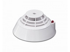
HEAT DETECTOR WIRE BUS ELECTRONIC ADDRESS CODING FIRE ALARM
$12.80
Description
Addressable heat detector 920E works with our addressable MN300 panel via a 2-wire bus system.
The detector realizes real-time acquisition of the heat concentration data and sends back the data to a fire alarm control panel. It can also receive and execute the control commands given by a fire alarm control panel.
The detector is suitable for such industrial and civil buildings that have a great deal of heat when fire takes place, such as kitchens, boiler rooms, generator rooms, drying workshops and smoking rooms and is not suitable for places with a great deal of smoke but little heat.
Product features
It can realize electronic coding and rewrite the address via coder.
With a single-chip microcomputer, it can realize real-time data acquisition and processing, realize a curve tracing for the field situation.
It has a temperature compensation function and a sensor fault detection function(fault reporting to fire alarm control panel).
Non-polarity, two-bus connection that ensures convenient installation and maintenance.
Designed with an upper cover and a lower cover and installed on an independent base, it can be installed, debugged and maintained conveniently.
Technical parameters
1.Executive standard: GB4716-2005
2.Operating voltage: 24V (pulse modulation)
3.Operating current: <300uA (monitoring status) or<1.5mA (alarm status)
4.Work indication: The red indicator will blink in the monitoring status or remain lit in the alarm status.
5.Weight: about 47g
6.Product class: A2
7.External dimensions: diameter: 100mm, height: 56mm (with the base)
8.Wiring method: non-polarity two-bus system (L1, L2)
9.Operating environment: Indoor, temperature: -10C~+50C; relative humidity: <=95% (40C±2C, without condensation)
10.Coding mode: It can realize electronic coding via coder in situ. Address codes 1 to 324 are available for selection.
11.Installation height: <=8m
12.Protection area: about 60m2. For details, see related provisions in GB50116-98 Code for Design of Automatic Fire Alarm System.
13 Installation and debugging
Determine the location, mounting distance and numbers for mounting the detectors in the protection area according to relevant provisions and regulations of GB50116-98 Code for Design of Automatic Fire Alarm System and GB50166-2007 Code for Installation and Acceptance of Fire Alarm System.
A self-contained complete base is necessary during the installation of a detector. As shown in Fig.5, the model, the external dimensions, the mounting hole diameter and the mounting hole spacing of the base are DZ-910, 100mm×22mm (diameter×thickness), 5mm and 56mm~64mm respectively.
Wiring requirement:
It is proper to use RVS twisted pairs with a section area of equal to or larger than 1.0mm2 for the signal buses L1 and L2.
SHARE THIS


