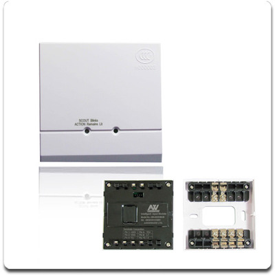
BUS TYPE ADDRESSABLE FIRE ALARM SYSTEMS INPUT/OUTPUT MODULE
$16.50
Description
The Intelligent Input/Output Module is used with MN300, a two bus linkage fire alarm control panel. It is mainly used to realize an output control for fire linkage equipment (such as smoke dampers, blow valves and fire dampers) and receive the feedback signals of the fire linkage equipment so that a judgment on whether or not the fire linkage equipment is operating normally can be done.
Features and technical parameters
1.Mode of operation: Nonpolar two-wire system
2.Quiescent current: <0.6mA (power-down mode)
3.Action current: <10mA
4.Capacity of the output control contact: 2A@DC30V
5.Operation indicator: The inspection indicator will blink once about every 12 seconds in the inspection status or remain lit in the output status; the input indicator will remain lit in the feedback status.
6.Operating environment: Temperature: -10C~50C; relative humidity: <=95% (40C±2C, without condensation)
7.Terminal load: 47K resistance
8.External dimensions: 86×86×40(mm)
9.Weight: about 130g
10.Executive standard: GB16806-2006
Installation and debugging
1.Make sure the type of the module matches the type given on the construction drawings.
2.Connect the 4 pin coding plug on the coder with the 4 pin coding socket (see Fig.1) on the main body of the module and then set the coder with the coding function and compile the correct address code to finish the address coding.
3.Conduct correct wiring as instructed in Fig.3 or Fig.4.
4.Use two M4 screws to fix the module base via the two elliptic screw holes shown in Fig.2 and then insert the main body of the module into the module base and make sure they contact each other well.
5.After the module is installed and checked, connect the power supply of the fire alarm control panel. Upon successful login, the inspection indicator of the module will blink once about every 12 seconds, which suggests that the module has begun to operate.
6.Conduct debugging after the installation is completed. Make the fire alarm control panel send out a starting signal and have the starting signal sent by the module to the fire linkage equipment connected with it. After that, the fire linkage equipment will operate correspondingly and the inspection indicator of the module will be lit. The operating fire linkage equipment will give a feedback signal. After receiving the feedback signal, the module will have its input indicator lit, which suggests that it has begun to operate normally.
7.After the debugging, reset the module and related equipment.
SHARE THIS


